{metacanonical:http://theprojectjunkie.com/bicycles-bike-components/homemade-carbon-fiber-bike-project.html}
Homemade Carbon Fiber Bike Project


Note: If you don't like to read there are videos throughout this article. Check them out below 
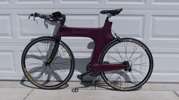
When I first mentioned that I wanted to build a homemade scratch built carbon fiber triathlon or Time Trial bike (TT Bike), my friends looked at me like I was crazy. They’re probably right but so far it hasn't killed me yet. And honestly, it’s a beautiful ride; smooth, light and comfortable. Of course I’m not the first that’s created a bike out of carbon fiber, but I am one of only a few that has done it out of their garage without the use of CNC machining and complex tooling methods. I opted for the plug and bag method- Which means I create a plug out of Styrofoam, wrap with carbon fiber and then vacuum-bagged it. I’ll explain more about the process later.
Materials Used
The entire frame is built out of the following materials:
- Extruded Polystyrene 2lb per ft^3 (Owens Corning's Pink Foamular or Dow's Blue foam)
- 6k, 11 oz Carbon Fiber- 5 Harness Satin Weave (I believe it was HexTow's AS4 carbon fiber)
- EZ-Poxy EZ 83
- 5 min Epoxy
- Cotton Flox
- 1/8" Thick Aluminum for Front Derailleur hanger
Note: If you are new to carbon fiber, here is an article I wrote that explains Carbon Fiber Basics - I tried to make it as easy to understand as possible.
A little background
I started doing Triathlons in the summer of 2009 and road my first tri on my mountain bike, an old Mongoose (When they were good bikes) chrome-molly frame that weighs at least 40 pounds, and has some tires with some serious treads- I know, amateur to the max! The only people I passed during the race were other people on mountain bikes and beach cruisers. On one down-hill portion of the course I couldn't pedal fast enough to get any more speed out of the bike and I was going so slow. People were effortlessly whipping passed me. When I got to the run I was exhausted and ran like a turtle. After that race I swore I would never use another mountain bike on a road race again.
I started looking into buying a Tri specific carbon fiber bikes, but man they are pricey. Since I had always wanted to build a road bike frame out of carbon fiber I thought this would be a great opportunity to do it. The funny thing is I really had no knowledge of bikes; But I wasn't going to let that stop me. The best way to learn about something is to create it yourself. Of course I wasn't ignorant to composites. I am currently building a composite experimental airplane which uses the same process of construction as I used on my bike.
I know… enough talking already! So here it is… how I created my first homemade carbon fiber tt bike.
How I started- I had to figure out what I wanted so here's the list:
Triathlon Specific
Light weight
Aero Dynamic
Decent Components
Nude Carbon Fiber Finish (Ability to see the carbon fiber layers)
The Design Challenge
I didn’t know enough about bike geometry and how it worked with bio-mechanics to feel comfortable designing my own biking solution. So I did the next best thing, I copied the geometry from another bike. I did know that a 54 cm frame worked for me and after a bit of Internet research I found the Trek Equinox TTX which became my first choice to copy- But let me clarify something here; I didn’t try copying every part of the bike; I just copied the positioning and angles of the wheels, bottom bracket, head tube, and seat post as they related to each other. Everything else was of my own design. In fact my headtube is longer and my standover is taller than the TTX's. So it's really not the same bike at all.
I thought about building a y-frame or beam-bike similar to trek’s Y-foil and Softride’s bikes. However, I kind of wanted a Union Cycliste Internationale or UCI compliant bike (The Tour De France is a UCI compliant race). Therefore, I started construction on a double triangle frame design. But as it turns out my bike still isn’t compliant for several reasons; the first being that the bike has to be in production and available to any rider that wants one. Plus the tubes cross sections ratios are too high around 5:1 compared to the UCI’s maximum, which I believe is 3:1 ratio. No problem though because most triathlons don’t follow UCI rules, in fact I don’t know of any that do. If you’re interested in the UCI bike frame Rules, here’s their link:Technical regulations for bicycles, a practical guide to implementation.
Choosing an Airfoil for Down and Seat Tubes
Most Airfoils don’t fall into the tube aspect ratio allowed by the UCI, hence the reason most TT Bikes don’t use standard airfoils. You’ll notice that almost all bike manufacture’s use what’s called a controlled diffusion (cd) airfoil. These airfoils usually have a lower aspect ratio which make them less aerodynamic than airfoils with higher aspect ratios. However, the lower aspect ratio gives the bike frame's tubes better strength/stiffness to weight ratios along both axis instead of just one axis. I think Ceepo has a good writeup on bike aerodynamics; You can read more by following this link- Ceepo Aerodynamics. Although their bikes are not UCI compliant, they make a killer triathlon bike. Here are a couple of pictures that I stole from Ceepo's site which helped me in my design.

(FYI if you’re not familiar with airfoils, these are cross-sectional images. The "Cd" you see stands for Coefficient of Drag)
After doing a lot of research I decided to go with an NACA 0020 airfoil. Why did I choose this one over all of the thousands of different airfoils? Well, I was looking for a few characteristics: 1) it had to be symmetrical, which means if you folded it along its center-line lengthwise, it would be the same; 2) it had to have a low Reynolds number, which is the drag coefficient (Cd)- I was looking for a low Reynolds number for around 30 mph; and 3) it had to have a low aspect ratio, for structural integrity. The NACA 0020, I felt, was the best airfoil for the job. Here is a picture of it.
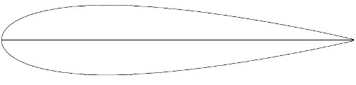
I used a program called Profili 2 to find my airfoil. Profili is manly used by RC airplane junkies, which I am also, for designing and building wings. I think it is a great program and it's free for finding and printing most airfoils. There is also a paid version which allows you to do more with airfoils and for the price I would recommend it to anyone that regularly works with, or needs airfoil designs. However, for building a bike tube the free version should work just fine.
Choosing a Bottom Bracket Shell

There are several types of bottom brackets used buy bike manufacturers and I needed to pick one out so I could incorporate it into the frame plans. I opted to use the currently most commonly used bottom bracket, the 68mm English threaded bottom bracket. I found an aluminum bottom bracket shell at Nova Cycle that would work for this application. It is a 69mm wide by 41mm diameter 7005 aluminum bottom bracket shell with a 1.37 x 24 TPI. Here is a link to Nova Cycles page English Threaded 7005 Aluminum Bottom Bracket.
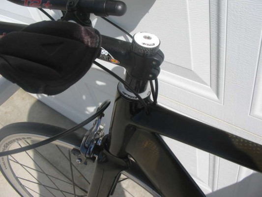
Choosing a Bike Headset

I needed to figure out which headset I wanted to use so I could design the head-tube. Choosing a headset was a lot more complicated than I thought it was going to be. There are hundreds of different styles and types to choose from and I wanted one that didn’t require extensive head-tube machining. I knew I wanted to use a non- treaded headset for a 1 1/8 inch steerer tube, but most non-threaded integrated headsets use a 36 or 45 deg non-cupped bearing which is not only press fitted into the head-tube, but also rests on 36 or 45 deg lips created inside the head-tube. After sifting through hundreds of headsets I found one that works with a straight head-tube, the Orbit Z by FSA. It is an internal headset with cups designed to press-fit into and rest on the head-tube’s rims. It was one of the more expensive headsets I found but worth the extra money to avoid having to machine the head-tube.
The dimensions of the Orbit Z required a head-tube with an inner diameter of 44mm and an outer diameter of 50mm. I couldn't find any premade aluminum or carbon fiber tubes with these dimensions so I ended up creating my own.
Choosing a Front Fork
With so much riding on the front fork I decided not to build my own. For one I didn’t want to stress test it (There’s just something about a front fork braking and going head first over the handle bars at 30mph that doesn’t appeal to me) and front forks are readily available from various sellers. All I needed was a standard fork for a 700cc tire with a 1 1/8 inch steerer tube and a 40mm rake.
I wanted a fork with an airfoil and found one I liked on eBay. It was an OEM for an unnamed company... But after purchasing it, I am 99% sure it is a Bontrager Fork designed for the Trek Equinox TTX. The fork is a bit heavy and it doesn't match my headtube like I wanted but it works good. If I were to do it again I would have chosen something different.
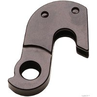
Choosing a Rear Derailleur hanger
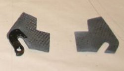
I went to the local bike shop to see what types of replaceable rear derailleur they had and to my surprise they had the perfect setup. It is a Cannondale A240/EBO replaceable road bike hanger that is designed to sandwich the dropout (see the image above). All I had to do was create the dropout with a certain amount of carbon fiber layers for it to work- Nice!
Choosing Tire Dropouts
I thought about aluminum dropouts but figured making my own out of carbon fiber would be easier and work just as well I think I used 9 layers and they have a slight angle on the part that inserts into the chainstay. So far they are working great and I haven't had any problems with them.
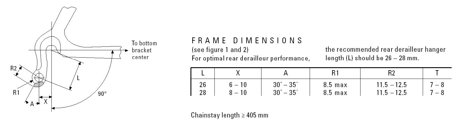
Aligning the Axle Hole with the Derailleur Hanger
This diagram helped me out a lot when trying to place the rear derailleur hanger. Here is a link to the source: Sram's Derailleur Hanger Specs
Drawing the Carbon Fiber Bike Plans
Now that I had all of my components I started my plans by plotting all of the bicycle’s base points; that is the dropouts (center of the wheel axels) in relationship to the center of the bottom bracket and etc. After plotting out the base points I was able to draw out the rest of the bike by drawing the geometry lines which showed me where to position the tubes and how to size them.
It's really not that hard to design your own road or tt frame. Here are a couple of things that will help you.
- Find the size of the bike you like and draw out it's geometry
- Draw your wheels-A 700c wheel's diameter is 622mm from fim to rim, but make sure you account for the tire's added size.
- Draw your tubes out from the geometry lines.
- The size of your head-tube's diameter will be determined by the size of the headset you are going to use.
- The size of your bottom bracket Shell hole will be determined by the diameter of your bottome bracket- My BB shell's diam is 41mm.
- The space for the rear wheel's axle or the space between the rear dropouts is 130mm- make sure you account for the rear derailleur hanger if it is a sandwich style you are using.
- Make sure the seat tube will accommodate the seat post shim or seat post.
Something you need to realize is that often times when you initially draw a set of prototyping plans the design will change as you go along. My initial plans look quite a bit different than the final product but the drawings will help you start somewhere. I like to start with full size drawings so that I can put things on it and visualize what I need to do when putting the bike together.
Carbon Fiber Bike Building Processes
There are several processes for building a carbon Fiber Frame. The most advanced and most commonly used currently is the bladder and mold method. This method works by laying carbon fiber in a shell mold were the carbon fiber is sandwiched between an inflatable bladder and the inside of the mold. The nice thing about this process is that the carbon fiber part comes out of the mold nearly finished. Some companies using this process will create the individual parts (e.g. down tube, seat tube, head tube, and etc.) and then bond them together in a jig. Other companies will create what is called a monocular frame. This type of frame is where the entire bike is created in the mold and nearly finished when it comes out- Most monocular frames, but not all, will still have the bladders inside them after production- that’s right the bladder stays in them forever. Lastly, some companies will use a combination of individual components and a monocular frame. Here is a cool video showing the clam-shell mold and bladder technique for a non-monocular frame.
The less common technique is the plug and bag method, which is the method I used- I'll show you the technique latter in the article. Basically you create a plug out of Styrofoam (e.g. the down tube, head tube, seat tube, chain stays, and etc.) then wrap the plug with carbon fiber and epoxy. After laying up the plug you vacuum-bag it to create a more compressed carbon fiber structure. Compression increases the carbon fiber to epoxy ratio making it lighter and stronger. Epoxy is the usually weaker and heavier than the carbon fiber but necessary for holding the carbon fiber strands together. Vacuum-bagging helps tighten the carbon fiber while eliminating excess epoxy, therefore making a lighter and stronger structure than not vacuum-bagging. On my bike I melted the Styrofoam plug out of some of the tubes once the structure was cured.
The most important part of bike building is keeping your base points parallel and in a correct relationship to each other (e.g. distance and position). The more parallel your wheel axles to your bottom bracket the better your bike will tract and your drive train will perform. It is also important to get the rest of your bike frame as perpendicular as possible to your base points. This will create a more comfortable ride and keep your bike’s stress points in a better position to avoid frame failure.
Building the Tubes
Very Simple Image Gallery:
Could not find folder /home/pm43nm074dyi/public_html/images/Carbon_Fiber_Bike_Build/Making_The_Tubes/
The tubes are constructed by creating a foam core, wrapping them in carbon fiber & epoxy, and then vacuum bagging them. As far as fiber orientation I have all my fiber bundles running at 0 and 90 degrees along the long axis of the tube. The tube plugs are cut using a hot-wire bow and templates. The templates are positioned onto the ends of precut foam blocks with great detail given to them being lined up correctly. The more lined up the templates the better your tube-plugs will come out. Once the tube-plugs are cut I clean them up with sand paper and either vacuum or brush them clean.
Downtube- 4 layers (foam melted out)
Seattube- 2 Layers (foam left in)
Toptube- 3 layers (foam left in with a center channel for running rear brake cable)
Headtube- 10 layers (created on a mandrel and then removed)
Seat Stay- 3 layers (foam melted out)
Chain Stay- 3 layers (foam melted out)
Rear Dropouts- 9 layers
Shaping and Fitting the Tubes
Very Simple Image Gallery:
Could not find folder /home/pm43nm074dyi/public_html/images/Carbon_Fiber_Bike_Build/Fitting_and_Shaping_the_Tubes/
I wanted the tubes to fit together well but I didn't get too anal over it. I knew that most of the gap issues would be eliminated when I added the flox and epoxy mixure to the joints. So I just got the tubes close enough to were I felt comfortable with it.
Jigging the Frame
Take a look at the picture below. Notice the jig on the left, I tried making it with some leftover aluminum angle that I had laying around and to make a long story short it was a disaster- Nothing lined up like it was supposed too and things kept moving around on me. Therefore I created the jig on the right, a much better solution. I took two boards and cut them out exactly the same. Then, I was very careful to line everything up so that that the frame sat in the jig correctly. This method worked great and was much easier to do than the jig on the left. Also note that you can see the bottom bracket shell ready to go in the jig. The bottom bracket shell looks amber because it has been wrapped in fiberglass. I don't know how necessary it is to wrap it in fiberglass but I read that corrosion and failure can occur when an aluminum shell has direct contact with the carbon fiber frame. The fiberglass acts like an insulator since carbon fiber and aluminum are both conductive materials.
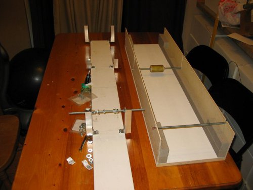
The easiest way to line everything up in the jig is to make sure that both sides of the part you are putting into the jig, are equal distances away from the sides of the jig. The rods used in the jig, if I remember right, was just 1/4" threaded rod. In order to make sure the seattube was perpendicular to the bottom bracket and front and rear axles, I pulled triangular measurements from the top of the seatpost to the top side of the jig wall- I made sure that both measurements were the same. I also used a "true angle" tool to make sure the headtube and seat tubes where at the correct angles (looking at the frame from the sides).
Once the frame was lined up inside of the jig I used electrical tape to secure everything and then did a type of "spot weld" with 5 min epoxy. You can see the results in the picture gallery below.
Very Simple Image Gallery:
Could not find folder /home/pm43nm074dyi/public_html/images/Carbon_Fiber_Bike_Build/Jigging_The_Frame/
Filling the Joints with Flox
Sorry about the following pictures and their quality- I took them off the Flip Camcorder, which is suppose to have 6 megapixel quality- Ya right!
Very Simple Image Gallery:
Could not find folder /home/pm43nm074dyi/public_html/images/Carbon_Fiber_Bike_Build/Floxing_The_Frame/
I decided to use cotton flox on the tube joints as a filler because it has excellent compressive properties and is extremely strong for bonding. The only downside to using it is that it's a bit heavy. The process for adding it to the joints was easy, just fill the spaces as good as possible. Nobody is ever going to see it so it doesn't need to be pretty but the stuff cures really hard and is tough to sand. The best thing to do is clean up the surrounding areas of the joint, where the flox is not needed, as well as you can before it cures.
Adding Carbon Fiber Reinforcement to the Frame Joints
Very Simple Image Gallery:
Could not find folder /home/pm43nm074dyi/public_html/images/Carbon_Fiber_Bike_Build/Joint_Reinforcements/
Not much to say here I wetted out some carbon fiber cloth and slapped it to the frame joints. I used at least 3 layers of carbon fiber on each joint. However, I believe the bottom bracket area received more- I was wrapping the joint and lost track of how much I was using I just kept wrapping until it looked good.
Using Epoxy as Filler/Leveler
Very Simple Image Gallery:
Could not find folder /home/pm43nm074dyi/public_html/images/Carbon_Fiber_Bike_Build/Epoxy_Finish/
So this was the longest process of the project, and I think it added some unnecessary weight. Would I do this type of finish again? NO WAY!!! I'm not kidding it took forever... I would put a layer of epoxy on and then sand it off. I would put another layer on and sand it off. I repeated this process probably a dozen times before I finally said it was good enough. So why didn't I just put a ton of layers of epoxy on and then sand it all down at once? Because of the blasted pinholes. They kept causing the epoxy to bubble up. I would sand the bubbles off and then put another layer of epoxy on and the bubble would come back. I eventually got them all but it took forever.
Note: I heard that heating the frame before adding the epoxy and then letting it cool down during the cure would help- Which I started doing after about the 4th coat of epoxy. It actually did help a lot but still didn't eliminate all of the bubbles for me after the starting the new process.
If I were to do it again I would have used epoxy mixed with micro balloons, or glass bubbles, as the filler. Once that process was done then I would just paint the frame.
Most carbon fiber bikes are able to achieve a beautiful nude carbon fiber finish because they are using a clam-shell mold. The bike comes out of the mold pretty much done. They just give the frame a light sand and then a coat of clear and that's that.
Because of all the coats of epoxy my finish is very much a greenish amber color. Somebody told me that it looks like a Carp (fish)! LOL it really does.
Adding the Mounts
Very Simple Image Gallery:
Could not find folder /home/pm43nm074dyi/public_html/images/Carbon_Fiber_Bike_Build/Adding_Mounts/
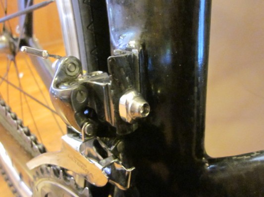
Front Derailleur Mount/Hanger
I tried just using a piece of aluminum angle for the front derailleur mount and then cutting a slot into it for the derailleur bolt. It didn't work. The tension from the shifting cable was too great and the derailleur would rotate instead of shifting. I ended up having to shave off the protruding aluminum angle and screwing on a new scratch built derailleur hanger. There are some pictures of it in the Bike Fixes section below.
Rear Break Mount
The rear break mount is just made out of 1/2 aluminum tubing. After mounting it with flox and reinforcing it with carbon fiber, I just drilled a hole for the brake caliper bolt. It worked great first time around.
Seat Clamp Construction
Very Simple Image Gallery:
Could not find folder /home/pm43nm074dyi/public_html/images/Carbon_Fiber_Bike_Build/Seat_Clamp/
I made the seat tube long so that I could use it as a plug for the seat clamp. I attached a 3/8" piece of plywood to the back of the cutoff seat tube, so that when it was squoze together it would create enough friction for the clamp not to slide up or down on the seat tube. However, this alone didn't work and it kept sliding down the seattube as I road the bike. I tried adding silicon to the inside of the clamp and also using rubber gaskets for more friction but that didn't work. After a few modifications I was able to fix the problem and will explain that in the Bike Fixes part in the next section of this article.
Another problem with the original seat clamp design was that the nose of the seat kept rotating down while ridding. This was because the mounting bracket was also not able to create enough friction on the clamp. Again I was able to fix the problem with some modifications, which is document in the next section below.
Bike Fixes and Modifications


Seat Clamp or Seat Post Modification and Fix
As stated before, the nose of the seat kept rotating down as I road the bike. So I replaced the mounting bracket with the top part of an Alien seat post. This actually turned out to be a much better modification than I had planned on, because I can now adjust the seat's angle/attitude by a bolt just under and behind the new bracket- Where as before I had to take the seat clamp off to change the seat's angle.
Front Derailleur Modification and Fix
The new Carbon Fiber Front Derailleur Hanger turned out quite well but it took me two "shots" to get it right. I used the a plug made out of 3/8" plywood and 3/8" dowel. You can see a picture of the plug above. It's called "plug mold for front derailleur hanger"- Hold your mouse pointer over the pictures to find it. I messed up on the first hanger by over working it- mostly from over-sanding and messing up the screw holes. It caused the derailleur to keep twisting. Luckily I made extra so I made another and it worked great. You can also see the new one on the video or picture gallery above.
Final Comments
I've ridden this bike for well over 500 mile now and it's been a great bike. However, I'm itching to do another design so stay tuned.
This project was a great learning experience for me and now I know a ton about bikes. I've been asked by quite a few people if I think they could build a bike. My answer to that is "Of course you can!" Why couldn't you? Just do the proper research, be smart, and take the appropriate safety measures- Like wearing a helmet when you're riding (and wearing shoulder, elbow, and knee pads when you're testing- OK that might be overkill but seriously be smart and be safe).
Carbon Fiber Z Frame
Here is a new bike that I built that is a bit more modern and "concept-ish" Here's a link to the article if you are interested- Carbon Fiber Z Frame Bike
Bike Building Resources
Here are some of the articles or websites that helped me starting out.
Damon Rinard's Carbon Fiber Beam Bike
This build is one I found while I was building my bike and was shocked at the simularities. Anyways, it's a good read and cool bike.
Yvon Dufour Hand Built Carbon Fiber Triathlon Bike
{stalker}